Logiciel libre de géométrie, d'analyse et de simulation multiplateforme par Yves Biton
Toutes les versions de cet article : [English] [Español] [français]
Since version 7.9 it is possible to modify dynamically the dimensions an image.
Il this tutorial I will shox you how to reproduce the figure at the bottom of this page.
We will use a predefined macro construction of MathGraph32.
Let us recall that these macro constructions are not included when downloading the software but may be downloaded on this page : Download of MathGraph32 version 9.2.
You can also download them underneath :

Once downloaded, you must expand this zip file in the directory of your choice..
You will also need an image you can download underneath (expand the zip file as well) :
Get MathGraph32 started (7.9 version or higher) and verify with icon options  (horizontal toolbar) that the level of use is Advanced level without complex numbers.
Use icon  to create a new figure without frame and with a unity length.
Expand the points toolbar an use icon  to create to free points you will name A and B.
Use icon  to create the midpoint of segment [AB].
Use icon  to measure length AB.
Now let’s insert our image as image linked to this midpoint.
Expand the dispalys toolbar and activate tool  (image lined to point), then click on the midpoint you just created.
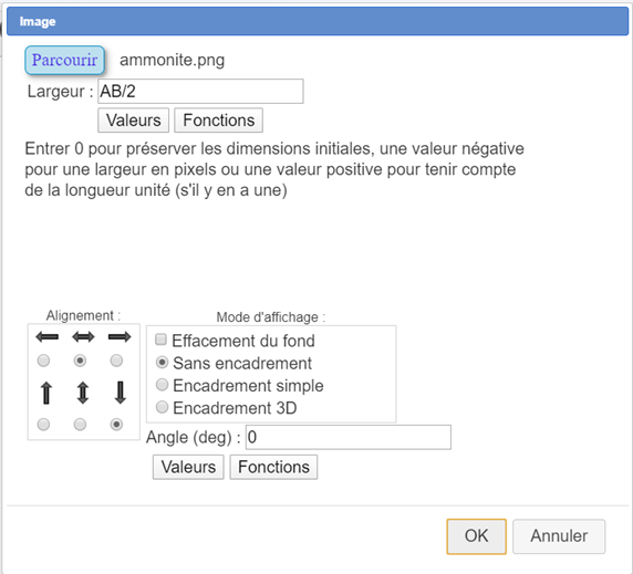
A dialog box pops up.
Use button Browse, browse to the directory you expanded the image file to, and click on button Open .
Fill in the dialog bow as shown underneath. Be careful to put AB/2 in the Width editor
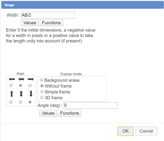
When capturing points A et B we see that our image remains horizontal. Indeed in the dialog box during the image creation, we let 0 in the Angle editor.
Here we have to use our macro constuction to set the angle dynamically.
In the upper toolbar, click on icon in order to get more icons.
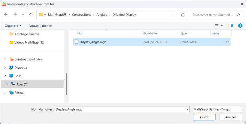
Use icon  (macro constructions management) and choose item Incorporate construction from file. Browse to the directory you expanded the macro constructions zip file to, open the directory Oriented display like underneath, select the file named Display_Angle as shown underneath and click on button Open.
This macro construction is now part of our figure and may be used.
Use icon and click on item Implement a construction of the figure. A dialog box pops up with our construction already selected. Click on button Implement.
On the top right corner of the figure is displayed : click on point A (for an oriented display from A toward B). Click on point A.
Then, in the same way, click on point B. Our construction is implemented.
To verify the impementation, in the upper toolbar, activate tool  (protocole tool),browse to the end of the objects list :
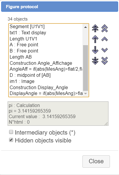
The construction implementation has created a calculation named DisplayAngle. It is this calculation we must use as value for the angle display of the image.
But the image was defined before the construction implementation. For now, the image cannot use the calculation DisplayAngle, unless we reclassify the image after DisplayAngle.
Staying in the protocole dialog box, select image (im1) the on the right clic on icon  . Your image is now at the bottom of the list. >Select im1 and click on icon
 (a double click on im1 works as well). The dialog box used for the image creation pops up.
Erase the zero in the Angle editor, click on button Values, go fetch DisplayAngle as underneath and validate.
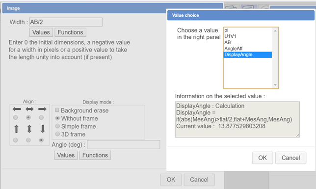
AngleAff has been pasted in the Angle editor. Validate by OK.
Now if you capture points A and B you will notice that the angle of the image is changing accordingly to the angle between segment [AB] and the horizon.
 Accueil
 Présentation
 FAQ
FAQ Contact