Logiciel libre de géométrie, d'analyse et de simulation multiplateforme par Yves Biton
Toutes les versions de cet article : [English] [Español] [français]
This article has been adapted to the Javascript version of MathGraph32.
Here we will explain how to create a construction on your own and how to use it.
Our goal is to create a construction which, given two points A and B and a numerical value ang, will create a triangle AMB rectangle in M such as angle BAM has ang for measure.
Let’s create a new figure with icon  (uppertoolbar).
If necessary, use icon ![]() to check that the angle unity of the figure is the degree.
to check that the angle unity of the figure is the degree.
Use icon  to create a calculus named ang containing 30 for formula.
Create two free points with icon  and give them A et B for name (use icon
  if you don’t name them on the fly) .
Use icon  to create the midpoint of segment [AB].
Use now icon  to create the circle with center the former midpoint and going through point A.
Let’s now create the image point of point B through the rotation of center A and angle ang.
For this click on icon  .
.
Now click on point A (rotation center) which starts blinking.
A dialog box pops up asking for the angle. Enter ang for angle value (you can use the Value button)
Click now on point B to create it’s image through the rotation.
Use now icon  to create the half line with origin A and going through the last point created.
With intersection tool  create the intersection between the circle and the half-line. Simply click at the intersection when displayed this intersection.
We will name this new point M.
Use icon  to create segments [AB], [BM] et [MA] and icon
  to create a right angle mark in M (click on A, then M, then B).
Our figure is now ready to create the construction.
For this we must make appear a few new icons.
In the upper toolbar, click on icon ![]() which makes appear new icons.
which makes appear new icons.
Use icon  and choose item Graphical sources objects choice.
Click on A, on B then click on red icon STOP (bottom right corner of the window)..
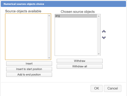
Use again icon and choose item Numerical sources objects choice.
A dialog box pops up.
The left list box contains numerical elements that can be chosen for sources objects. Click on ang the click on button Insert (you can also double-click on ang) then validate as shown underneath.
We must now indicate the final objects of our construction. In this example, final objects will only be graphical objects.
Mathgraph32 allows the user to choose for final objects exclusively objects created only with the sources objects.
Use again icon and choose item Graphical final objects choice.
Click on point M, on the three segments, on the angle mark then click on the red STOP button.
To get the construction finalized, use menu item and choose item Finish current construction.
Fill in the dialog box as shown :
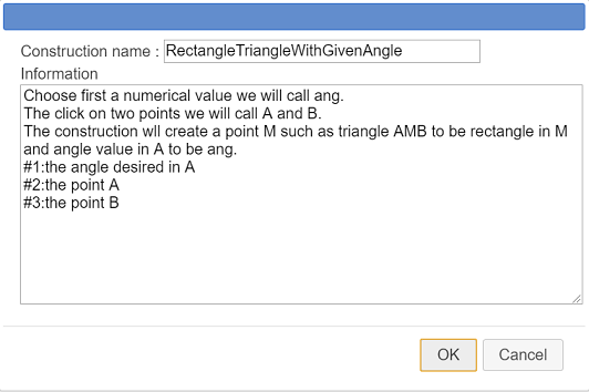
Here is the content of the input :
Choose first a numerical value we will call ang.
The click on two points we will call A and B.
The construction wll create a point M such as triangle AMB to be rectangle in M and angle value in A to be ang.
#1:the angle desired in A
#2:the point A
#3:the point B
Here are explanations about the informations entered in the edit text box.
The last three lines will indicate the user which is the source object he must indicate when implementing the construction.
Each indication starts with character # followed by the number of the object and a character : .
To be noticed : When implementing a construction, numerical objects are to be chosen first.
If you don’t delete this construction, it will be saved in the file along with the figure but it is better if you save it in a mgc file on disk.
For this, use icon  .
.
A dialog box pops up, displaying all the constructions contained in the figure. Our only construction is already selected.
Click on button Save to save this construction in the directory of your choice (it is better to keep the samme name for the file as the construction itself).
We will now show how to implement this construction in another figure.
Use icon to create a new empty figure.
Use icon  to create a variable named a with - 90 for mini value - 90, 90 for maxi value, 10 for increment step, 30 for current value and set the checkbox Associated dialog selected.
Create two free points with icon et name them C and D.
Use icon , choose item Incorporate construction from file and open the construction you saved before (you must browse to the directory where the mgc file was saved before). This contruction is now part of your figure and is available.
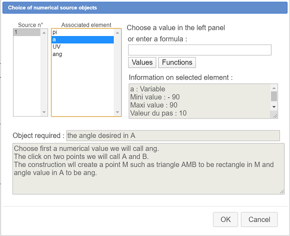
Again use icon and choose item Implement a construction of the figure.
A dialog box pops up for the choice of the real value that will be the angle (named ang when the construction was created).
Click on a in the list as shown underneath.
Then click on points C and D as asked on indications on the top right corner of the figure.
Now you can see the final objects created : the three segments, the point M and the right angle mark.
Clicking on buttons + et - of the little dialog box associated with the variable will modify the angle value in point C.
To be noticed : In more sophisticated constructions you can have also numerical final objects.
Using icon  key (for the figure protocol display) and selecting the checkbox Intermediary objects you will see how the figure was created.
Intermediary objects cannot be used to create other objects, unless you use icon and choose item Merge constructions of the figure.
An important remark :
In an usal usage, free points are not supposed to become fianl objects, but, in some cases, it may be useful.
For a free point to become a final object, choose first the free point as graphical source object. The choose this point as final object.
 Accueil
 Présentation
 FAQ
FAQ Contact